Request a quote

Engineering Confidence

Process, Testing and Documentation

Present materials, test methods and certification conclusions separately so that every disclosed content can be traced back to specific specifications and official documents.

LSW wheel testing

MATERIALS & PROCESS

From within the material,
Build reliability.

Forging, heat treatment and five-axis finishing form the structural manufacturing process. Material selection, equipment capability and machining requirements depend on the specific product and formal engineering drawings.

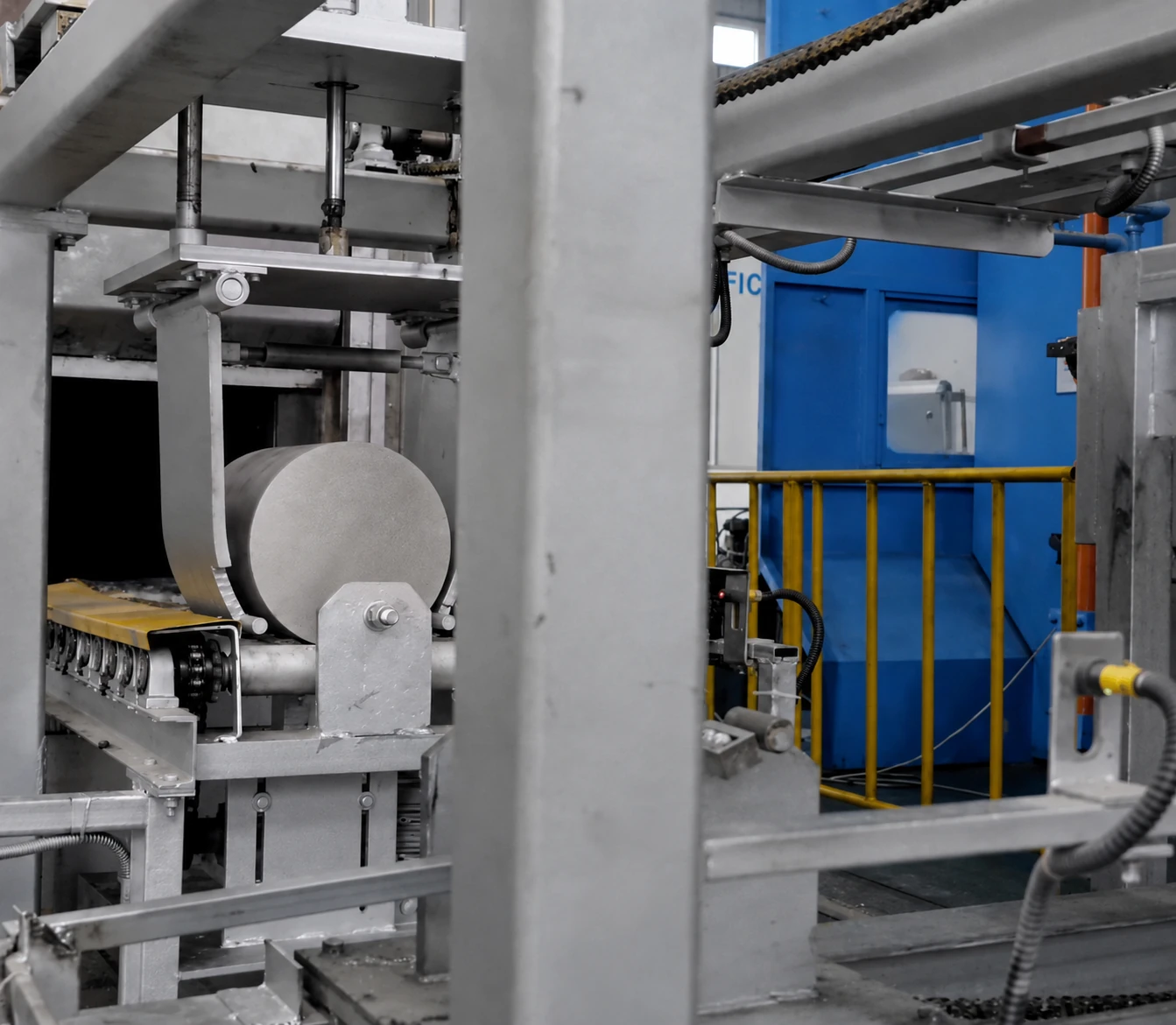
6061-T6 aluminum alloy cylindrical blank in LSW factory material preparation equipment

Alloy grade and temper are different specifications

6061 is a heat-treatable 6xxx-series aluminium alloy grade. T6 describes a condition achieved through solution heat treatment and artificial ageing. The grade identifies the alloy system; the temper describes the heat-treatment route. A “6061-T6” label on a page does not replace batch material certification, heat-treatment records or test results from finished-product samples.

Forging controls how the material flows

Under controlled temperature, tooling and pressure, the billet undergoes plastic deformation to form the rough geometry of the hub, spokes and rim. The process is intended to fill that geometry consistently and retain the correct machining allowance—not to infer finished-wheel performance from a material name alone.

The T6 Temper Must Be Confirmed by Process and Inspection

Solution treatment, quenching and artificial ageing influence microstructure and mechanical properties. The specific process window is a controlled manufacturing parameter. Any published claim should link the heat-treatment batch to hardness, tensile or other specified inspections. This article does not provide temperatures, times or performance figures unsupported by company records.
Learn More
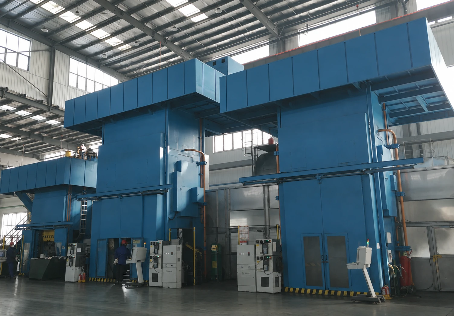
LSW factory 6000T, 12000T and 800T three-level forging equipment production line site

Three-stage forging is a sequence of operations

Available information shows a line comprising 6000T, 12000T and 800T forging presses. The important context is the role each station plays in billet preforming, main forming and subsequent sizing or process transfer—and how the workpiece remains controlled between stations. Adding the tonnage figures together does not describe product performance.

Tonnage Is Not a Quality Conclusion

Press tonnage states nominal pressure capacity. It is not the actual forming load for a particular wheel and cannot, by itself, establish strength or fatigue life. The process also depends on billet dimensions and condition, die geometry, contact conditions, temperature, the pressing sequence and equipment condition.

Progressive Forming Supports Consistent Material Distribution

Multi-stage forming can divide major geometric changes across several operations, guiding material progressively into the hub, spokes and rim while retaining suitable allowances for heat treatment and finish machining. Achievement of the intended result must be confirmed through forging dimensions, surface condition, remaining machining allowance and any required internal-quality inspection.

Learn More
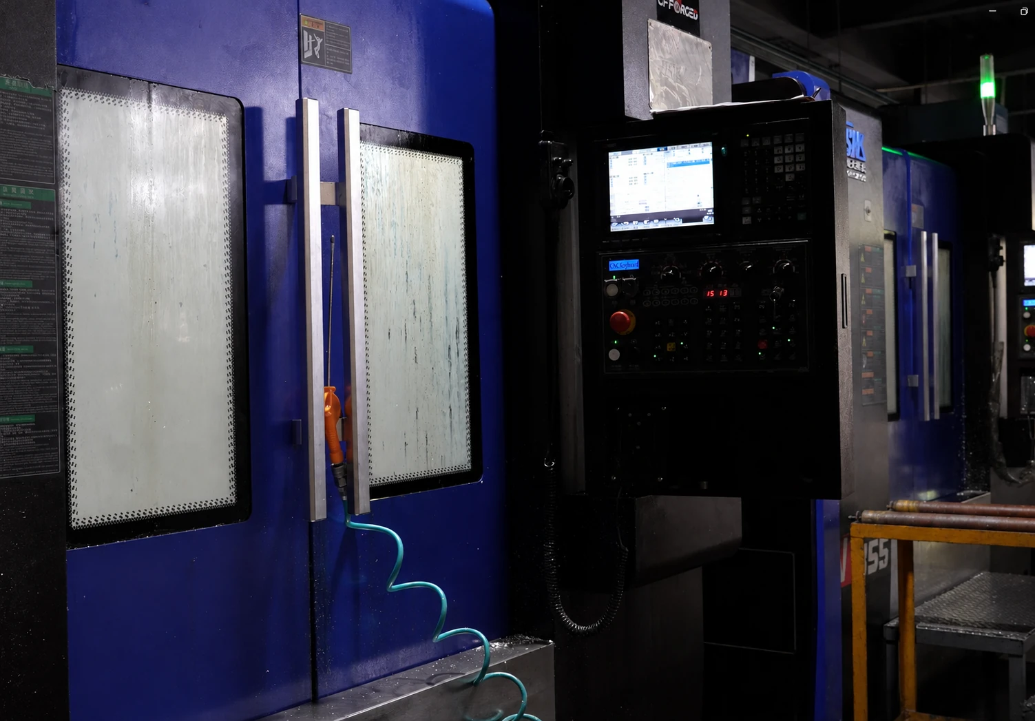
LSW factory five-axis CNC precision machining center equipment site

Five axes describe machine movement

A 5-axis CNC system combines three linear axes with rotary motion to change the orientation of the workpiece or cutting tool, improving access to spoke sidewalls, windows, rear surfaces and complex transitions. It describes a machining capability; it does not automatically establish a dimension, tolerance or surface-finish result.

The Datum System Defines Geometric Relationships

Wheel machining requires consistent location and datum transfer across the mounting face, centre bore, bolt holes, rim and spokes. If the fixturing method cannot reproduce those datums consistently, the same programmed tool path can still produce positional or geometric variation.

Program, Tooling and Measurement Form a Closed Loop

The CNC program defines the path, tool condition affects the actual cut, and measurement results determine whether compensation or a process stop is required. Different regions may use different roughing, semi-finishing and finishing strategies. Tolerances, surface roughness and inspection frequency must follow the product drawing and quality plan.

Learn More

Validation Programme

Four tests

The following shows the purpose and on-site materials of the four experiments. Equipment and process images do not represent compliance with any specification; formal methods, conditions, conclusions, applicable specifications and report numbers are subject to corresponding documents.

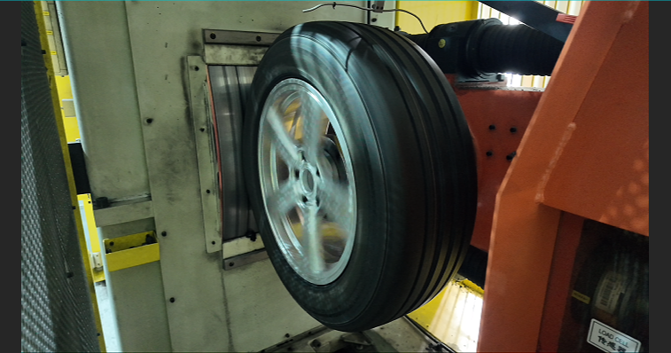
Simulate continuous radial rolling load and observe the durability response of the rim and spokes.

Tire hub assembly in LSW factory radial fatigue testing facility

The Test Simulates Sustained Radial Rolling Action

A radial fatigue test typically places a tyre-and-wheel assembly on test equipment, applies load and rolls it continuously so the rim and spokes repeatedly experience radial loading representative of straight-line driving. It evaluates durability under cyclic action; it does not reproduce every load condition encountered on the road.

Input Conditions Determine Whether the Result Can Be Interpreted

The report should identify the sample and specification, tyre and inflation conditions, mounting method, load setting, cycle requirement, stop conditions and applicable standard or customer specification. Without that context, footage of the equipment running cannot establish a result, and the conclusion for one sample cannot be extended to the full product range.

Process Monitoring and Post-Test Inspection Are Equally Important

Equipment and sample condition should be monitored as specified throughout the test, with anomalies, stops and adjustments recorded. After the required procedure, the rim, spokes and mounting area must be inspected for cracks or abnormal deformation as the method requires, with images and records linked to the sample.

Learn More

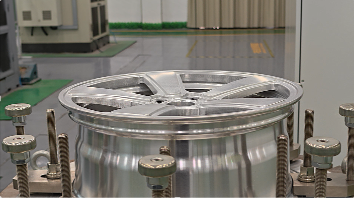
Simulate the cyclic effect of lateral moments and check the structural response of the wheel center, mounting surface and spokes.

Forged wheel fixed on bending fatigue test bench at LSW factory

The Cornering Load Case Focuses on the Lateral Moment Path

Steering and lateral forces travel through the tyre and wheel to the mounting interface. A cornering fatigue test repeatedly applies a bending moment on a controlled rig to observe the response of the hub, bolt holes, mounting face, spokes and transition regions under cyclic load.

Fixturing and Lever-Arm Geometry Are Essential Context

Test fixturing, loading-arm geometry, target moment, speed or cycle count, fastening method and equipment calibration all affect interpretation. The report should also state the sample model, size, offset, material and manufacturing batch so that equipment capability is not misrepresented as a conclusion for the entire range.

Observe Structural Changes, Not Merely Machine Rotation

Abnormal noise, displacement, loosening or equipment stops should be recorded during testing, with interim or post-test inspections performed as required. Areas of potential interest include hub-to-spoke transitions, the vicinity of bolt holes, the mounting face and local section changes.

Learn More

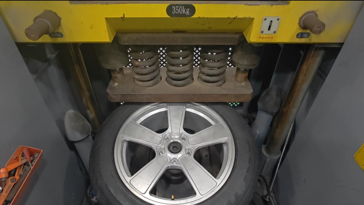
Simulate transient impacts in prescribed arrangements to evaluate structural response in critical areas.

Tire hub assembly and impact block in LSW factory 13° impact test equipment

Impact Testing Examines a Short-Duration High Load

Unlike the sustained cycles of a fatigue test, an impact test uses defined conditions such as mass and drop height to create a transient event and observe the structural response of a tyre-and-wheel assembly in a specified setup. The 13° angle is one geometric condition used in common test arrangements and cannot be interpreted apart from the complete method.

Impact Energy Comes from a Controlled Set of Inputs

Before testing, the sample, tyre, inflation pressure, mounting orientation, impact location, impactor condition and method requirements must be confirmed. Drop mass, drop height and any other energy settings must come from the applicable standard, specification or customer requirement. This site has not received those figures and makes no assumptions about them.

Post-Test Inspection Determines How a Conclusion Is Reached

After impact, the applicable method should be followed to inspect tyre retention and any visible damage, cracking, separation or abnormal deformation of the rim and spokes, with findings recorded against the method’s definitions. Photographs can support traceability but do not replace the prescribed acceptance procedure.

Learn More

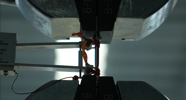
Record the mechanical response of materials under tension through standardized specimens and correlate sampling with batches.

Aluminum alloy specimen between the chucks of LSW factory material tensile testing machine

A Tensile Test Measures Material Response under Tension

A standardised specimen is loaded in uniaxial tension while the machine records the relationship between load and deformation. The relevant mechanical properties are then calculated according to the stated method. Terms such as tensile strength, proof strength or yield-related values, and elongation after fracture must correspond to the specific standard and report fields.

Sampling Determines What the Result Represents

Whether a specimen is taken from incoming material, a forging or a finished-product location—and the orientation in which it is taken—affects the material condition represented by the result. The report should link the alloy grade, heat or production batch, heat-treatment condition, sampling location and direction, specimen dimensions and preparation method.

Values Must Be Published with the Method and Units

A standalone “strength figure” is easily misread. Specimen geometry, strain-measurement method and the selected standard affect field definitions and calculations, so units, method, results and acceptance requirements should remain together in the report. This site has not received batch-specific results and therefore provides no illustrative pass values.

Learn More

Documents and Standards

Documentation and Scope

The following documents are classified into manufacturer registration, test equipment accreditation, third-party voluntary documents and management system documents respectively; their subject, scope of application, validity status and whether they can support specific product claims are subject to the original documents and corresponding reports.

Understand the basics of JWL / VIA certification system Ask About Quality and Certification
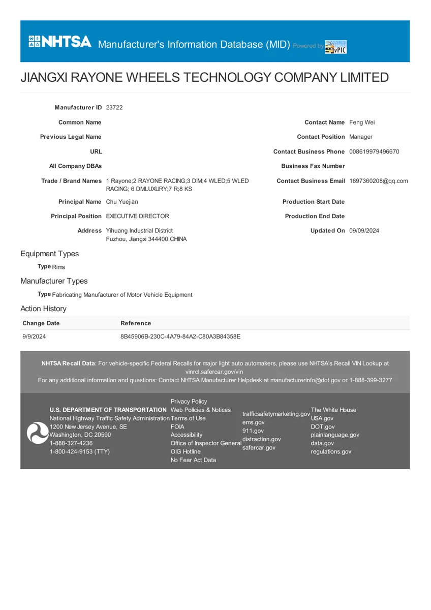
Jiangxi Ruiyun Cheng Technology Co., Ltd. NHTSA manufacturer information database registration document cover
01 / US Manufacturer RegistrationDatabase Registration

NHTSA Manufacturer Registration

Manufacturer ID 23722

Manufacturer database registration does not represent product approval or certification

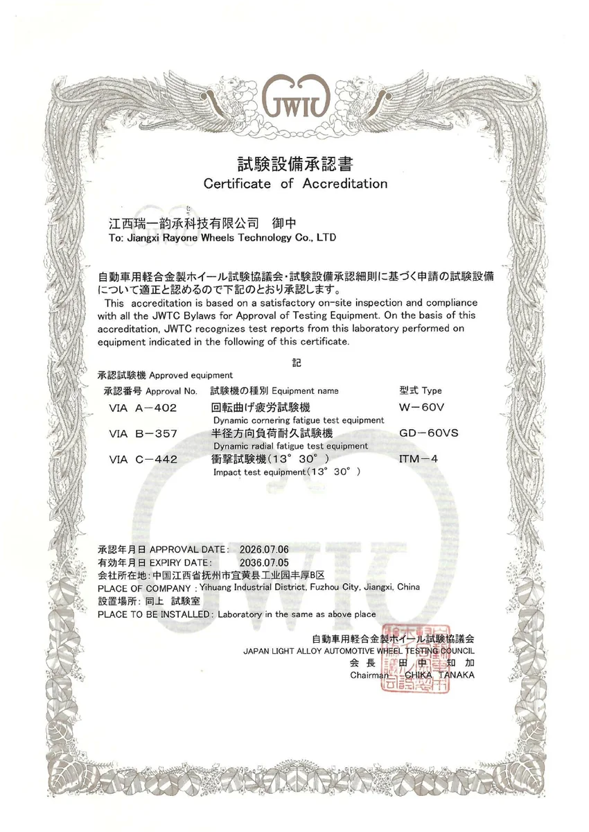
LSW forged wheel VIA test equipment approval certificate cover
02 / Test equipment approvalEquipment Accreditation

VIA Test Equipment Approval

JWTC · VIA A-402 / B-357 / C-442

Covering bending, radial fatigue and impact testing equipment

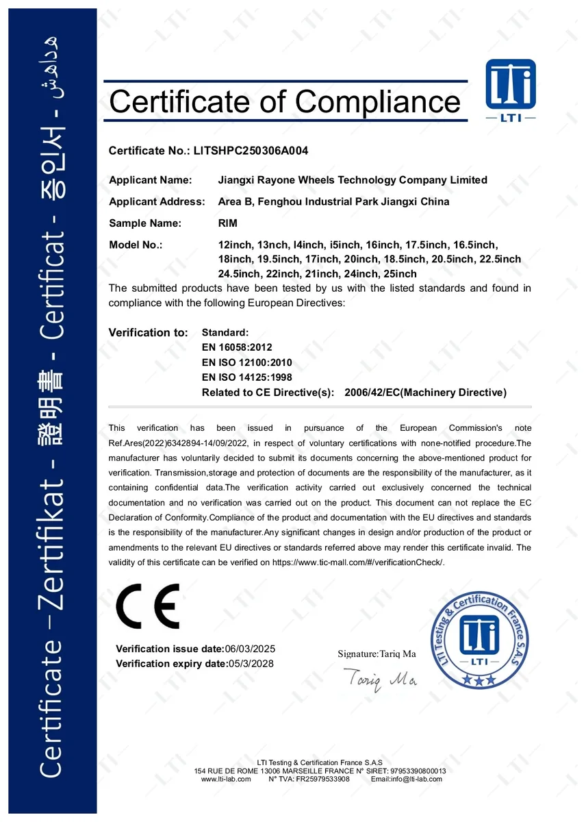
Cover page of third-party voluntary compliance document, applicability is subject to special review
03 / Third-party voluntary documentsApplicability is subject to special review

Third Party Voluntary Compliance Document

LTI Testing & Certification France

No. LITSHPC250306A004; shall not be used as evidence of wheel product compliance or safety certification

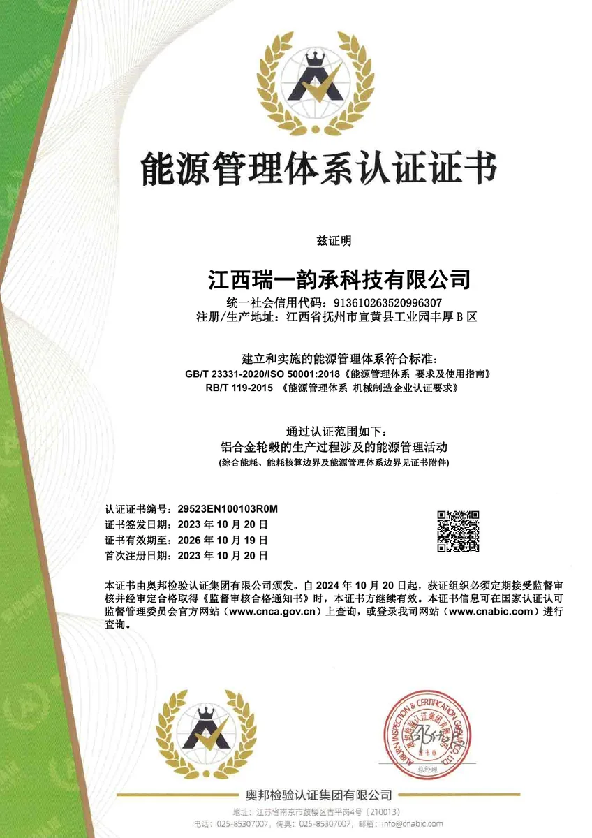
Jiangxi Ruiyuncheng Technology Co., Ltd. ISO 50001 Energy Management System Certification Certificate Cover
04 / Energy Management SystemEnergy Management

ISO 50001 Energy Management System

GB/T 23331-2020 / ISO 50001:2018

No. 29523EN100103R0M

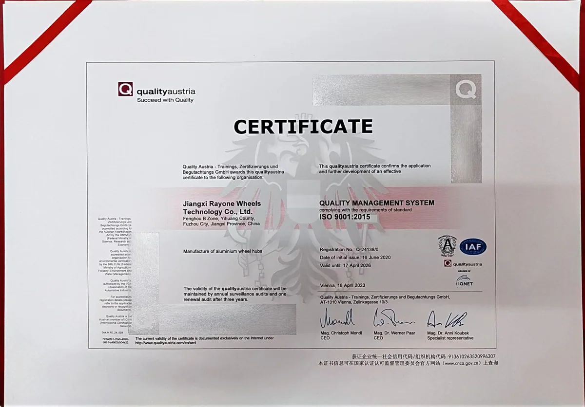
Jiangxi Ruiyun Cheng Technology Co., Ltd. ISO 9001 Quality Management System Historical Document Cover
05 / Quality Management SystemHistorical file · Expired

ISO 9001 Quality Management System

ISO 9001:2015 · Q-24138/O

The original document is valid until 2026-04-17; it will not be displayed as a current valid qualification.

Full certificates are available on request — contact our team and we will send the complete documents.

Identify the product before reading the document.

Start with the product you are considering. Note the model, dimensions and intended configuration, then review the sample identification and scope in the documents. A similar appearance or shared collection name does not establish that a document applies to every product.

Let the documents answer specific questions.

Images and summaries provide an introduction; full documents support a closer review. When requesting information, specify whether you need material details, test methods, product scope or purchasing documents, and include the target model and dimensions.

Move from a test introduction to documented results.

An introduction explains the purpose and process of a test; the report identifies the sample, conditions and conclusions. Read them together: which sample was tested, under what conditions, what was recorded, and how does that relate to your chosen specification?

For unclear items, keep the document name, page number and question together with the model and size. This makes follow-up discussion easier. Connect product selection, specification checks and document review so decisions rest on specific information rather than a logo or photograph alone.

Request product information