

Impact Testing Examines a Short-Duration High Load
Unlike the sustained cycles of a fatigue test, an impact test uses defined conditions such as mass and drop height to create a transient event and observe the structural response of a tyre-and-wheel assembly in a specified setup. The 13° angle is one geometric condition used in common test arrangements and cannot be interpreted apart from the complete method.
Impact Energy Comes from a Controlled Set of Inputs
Before testing, the sample, tyre, inflation pressure, mounting orientation, impact location, impactor condition and method requirements must be confirmed. Drop mass, drop height and any other energy settings must come from the applicable standard, specification or customer requirement. This site has not received those figures and makes no assumptions about them.
- Sample model, size, offset and batch
- Tyre specification, inflation pressure and assembly condition
- Impact location, orientation and equipment setup
- Post-test inspection method and failure criteria
Post-Test Inspection Determines How a Conclusion Is Reached
After impact, the applicable method should be followed to inspect tyre retention and any visible damage, cracking, separation or abnormal deformation of the rim and spokes, with findings recorded against the method’s definitions. Photographs can support traceability but do not replace the prescribed acceptance procedure.
Do Not Extrapolate One Test Image to Range-Wide Performance
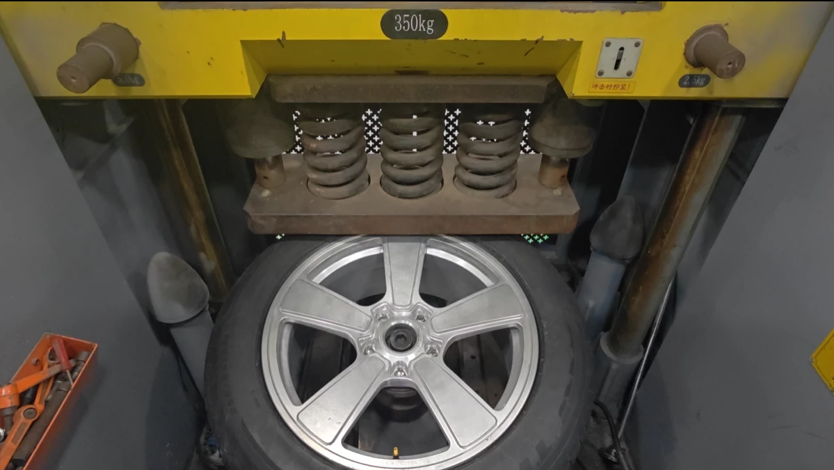
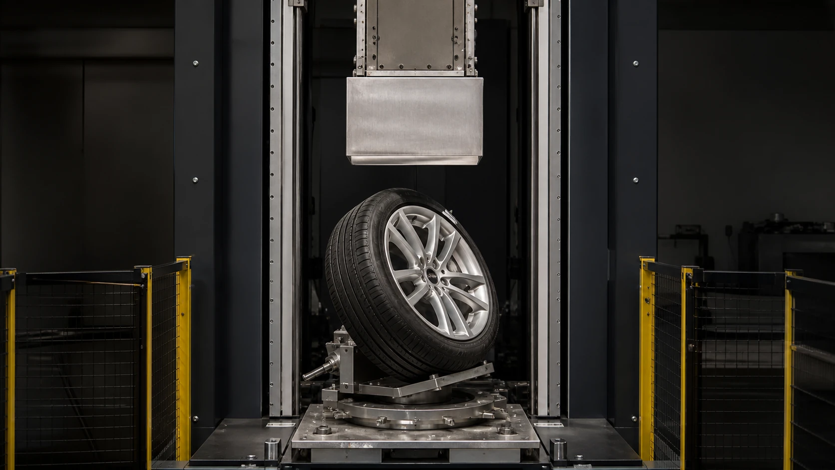
The available media shows a 13° impact test environment but provides no test conditions or conclusion. Different sizes, constructions, load variants and tyre configurations may require separate validation. Any conformity statement should identify the relevant sample, method, date and report number.
13° Where does the angle come from?
13° is the inclination angle setting used to fix the tire hub assembly in some wheel impact test methods. The purpose is to allow the impact block to act on the rim edge at an angle close to the vehicle hitting the curb or pothole edge, rather than a vertical frontal impact. This geometric arrangement comes from the simplification and unification of real road impact scenarios by relevant standards to facilitate comparable testing between different laboratories.
It should be noted that different standards or different test items may stipulate different impact angles, impact body shapes and energy settings. 13° is just one of the common configurations and cannot be used as a basis for judgment independently of specific standards and test conditions.
Next Step