

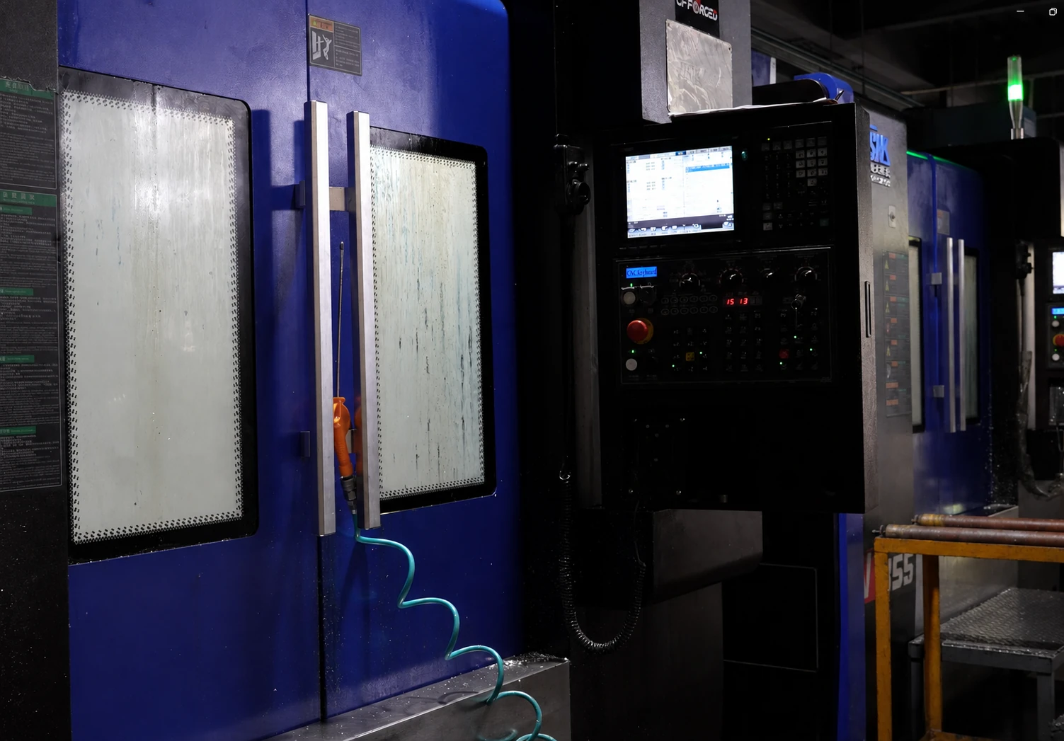
Five axes describe machine movement
A 5-axis CNC system combines three linear axes with rotary motion to change the orientation of the workpiece or cutting tool, improving access to spoke sidewalls, windows, rear surfaces and complex transitions. It describes a machining capability; it does not automatically establish a dimension, tolerance or surface-finish result.
The Datum System Defines Geometric Relationships
Wheel machining requires consistent location and datum transfer across the mounting face, centre bore, bolt holes, rim and spokes. If the fixturing method cannot reproduce those datums consistently, the same programmed tool path can still produce positional or geometric variation.
- Forging location and fixturing repeatability
- Mounting-face, centre-bore and bolt-pattern datums
- Tool length, wear and compensation records
- First-off, in-process and final-part measurement records
Program, Tooling and Measurement Form a Closed Loop
The CNC program defines the path, tool condition affects the actual cut, and measurement results determine whether compensation or a process stop is required. Different regions may use different roughing, semi-finishing and finishing strategies. Tolerances, surface roughness and inspection frequency must follow the product drawing and quality plan.
Machine Type Alone Does Not Establish Machining Accuracy
Equipment imagery can show the machining environment, but product accuracy requires supporting evidence from calibrated measuring equipment, defined methods, environmental conditions and relevant inspection records. This article does not publish unprovided machining tolerances or imply that the presence of 5-axis equipment proves any product specification meets its drawing.
General sequence of roughing, semi-finishing and finishing
After the forged blank enters machining, rough machining is usually performed first to remove most of the machining allowance and determine the basic outline, then semi-finishing is performed to correct the shape and reserve a uniform margin for finishing, and finally the key dimensions, surface roughness and assembly features are completed by finishing. Staged machining helps control cutting forces, reduces workpiece deformation, and makes it easier to optimize tool wear and cutting parameters individually for each stage.
After the processing is completed, the key dimensions and geometric tolerances are usually checked using a three-dimensional coordinate measuring machine (CMM) or special inspection tool, and the results are compared with the process card and product drawings. The measurement methods, sampling ratios and judgment standards are specified by the quality plan, and the specific values are not discussed in this article.
Next Step