Request a quote

THE ART OF FORGING

Forging technology

Forging is an engineering system—from material and structure to vehicle data and validation.

Forging allows the grains to extend along the direction of stress on the spokes, reducing possible internal defects in the casting structure.
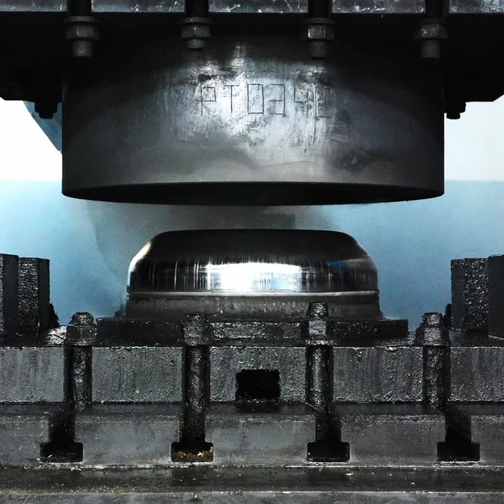
LSW Continuous grain manufacturing process of high-pressure forming of aluminum forged wheel billets in hydraulic forging dies

Grain flow is an internal material feature

Continuous grain flow here refers to the internal direction of material flow during plastic deformation, not to a visible pattern on the finished surface. Under the combined influence of temperature, pressure, tooling and the deformation sequence, the aluminium billet flows to form the underlying structure of the hub, spokes and rim.

Control Begins with the Billet

Billet grade, initial dimensions, thermal condition and surface quality all influence subsequent deformation. Material and process requirements must be confirmed before pressing so that the billet enters the die under specified conditions. The final shape alone cannot replace verification of the incoming material and process records.

Direct Material Flow to Serve the Structure

The forging process must move material into the geometry of the hub, spokes and rim while maintaining stable transitions in thickness, radii and local deformation. The engineering objective is not simply greater pressure, but a repeatable structural foundation within the capabilities of the equipment, the constraints of the dies and the defined process window.
Learn More

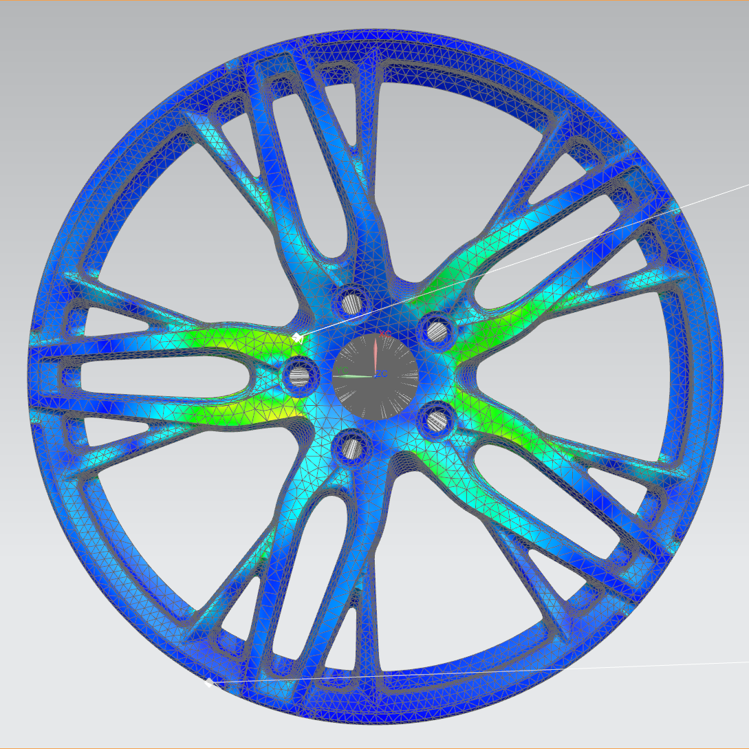
Perform finite element analysis for impact, bending and radial loads, iterate key areas, and perform back milling to reduce weight where the structure allows.

Finite element analysis structural optimization and load distribution diagram of LSW forged wheel

Analysis Begins with Boundary Conditions

A finite-element model must define material properties, interfaces, constraint locations and the way loads are applied. Radial, cornering and impact load cases are different; calculation results are meaningful for engineering purposes only when the boundary conditions correspond to the intended load case.

First, Understand How Loads Travel

The analysis is not limited to finding a single maximum value. It also examines how loads travel from the mounting face through the hub and spokes to the rim, and whether changes in local stiffness create unnecessary stress concentrations. Mesh quality, contact definitions and geometric simplifications also affect the result.

Give Each Iteration a Clear Purpose

The engineering team can revise spoke sections, fillets, thickness transitions and back-milled areas, then compare the designs under the same load conditions. Weight reduction requires a clear understanding of load paths and compliance with structural requirements; colour plots alone are not a basis for removing material.

Learn More

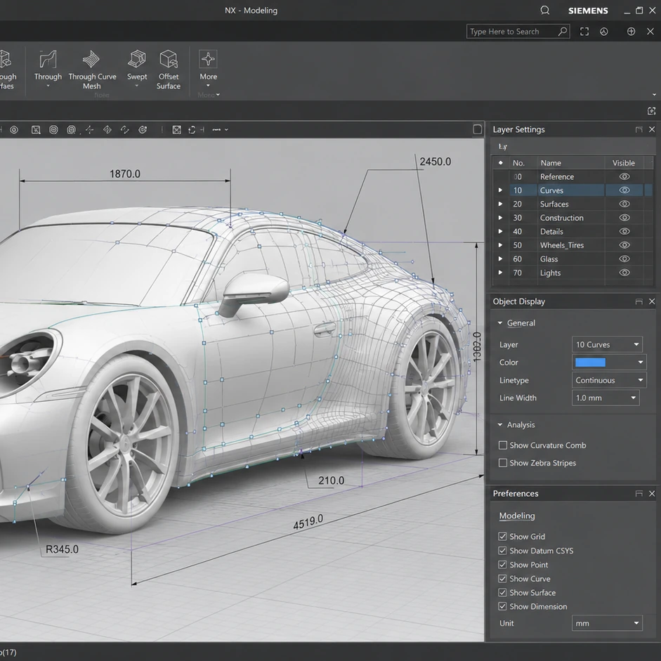
Wheel diameter, width, ET, PCD, center hole, load and caliper space are collaboratively verified in the same vehicle model.

LSW forged wheel vehicle parametric engineering, vehicle size and wheel arch adaptation modeling in Siemens NX

Establish the Vehicle Baseline First

Vehicle parameterisation involves more than entering a model name. Model year, generation, exact variant, drivetrain, original tyres, brake system, axle loads and suspension condition can all change the available space. The vehicle context must therefore be organised into verifiable inputs first.

Check Mounting and Clearance Together

PCD and centre bore define the basic mounting interface. Wheel width and ET determine the wheel’s position relative to the suspension and fender. Tyre diameter and section width affect the dynamic envelope, while the caliper profile requires a 2D template or 3D data. No single parameter represents complete fitment.

Parameter Changes Require a Linked Review

When wheel width, ET, tyres or brake configuration changes, inner and outer positions and dynamic clearances change with them. A parametric model keeps these variables linked so engineers can compare specifications efficiently rather than relying on isolated rules of thumb.

Learn More

Forging sequence

From aluminum billet to wheel

High-pressure forming, spinning, heat treatment and precision machining jointly determine the final structure and do not rely on a single process.

Each stage receives the result of the previous one and prepares for the next. Follow material preparation, forming, heat treatment and machining to see how the design emerges. Process arrangements and inspections relate to the specific product.

01

Pre-forging

Establish basic material flow direction

02

Forming

High-pressure shaping of spokes and rims

03

Heat Treatment

Stable strength and material condition

04

Finish Machining

Presenting the final structure and accuracy

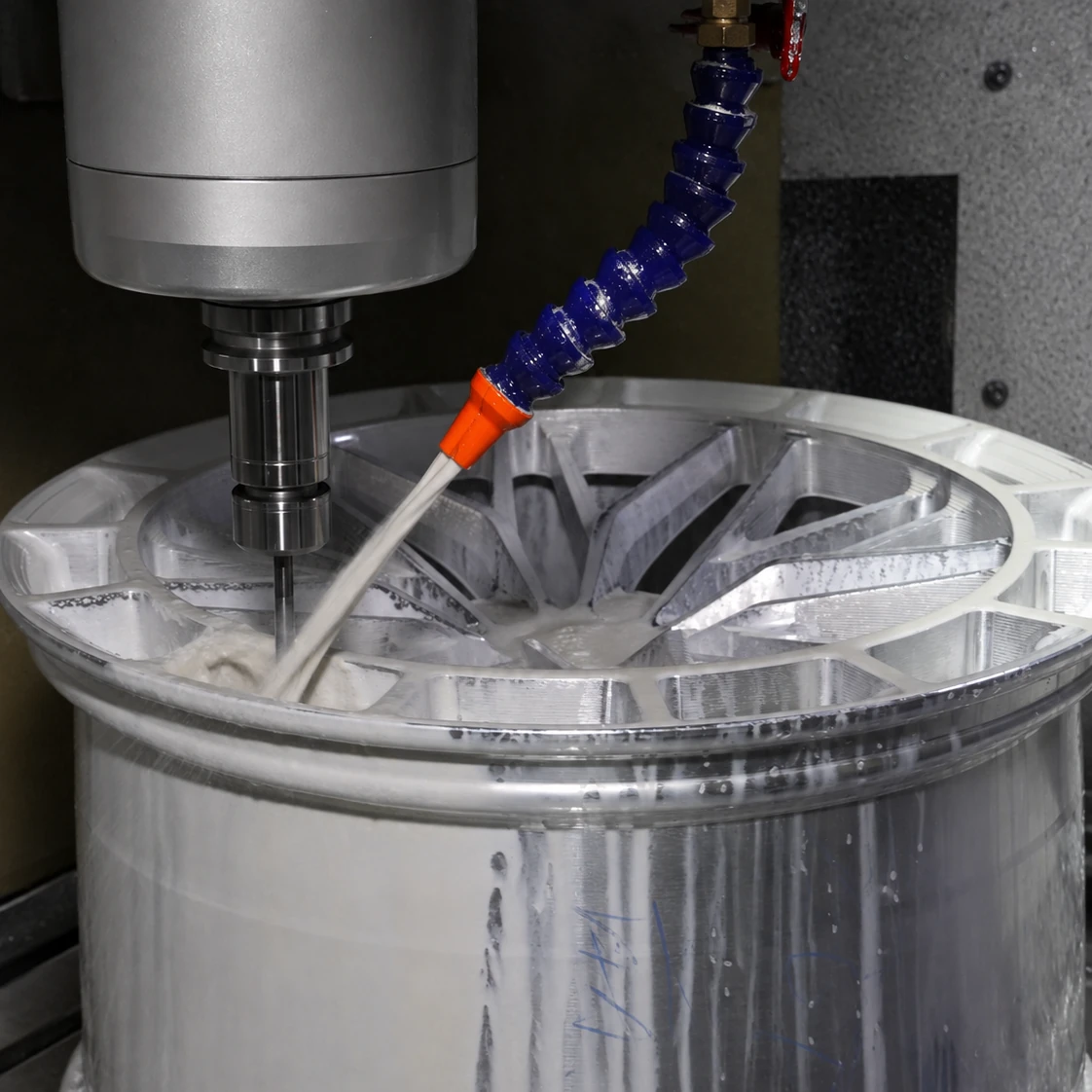
Precision back-milling detail on an LSW forged wheel spoke

LESS MASS, MORE CONTROL

Less weight.
Same integrity.

Truly effective lightweighting requires knowing how loads travel through the wheel centre, spokes and rim. Through finite element analysis and physical verification, materials are retained where needed and removed from inefficient areas.

Unsprung mass
More direct response
Rotational inertia
Acceleration and braking are sharper
Structural efficiency
Clearer load path

Vehicle-Specific Engineering

Designed
with the vehicle.

Same diameter does not equal same fit. Brake calipers, suspension, wheel arches, load and tires all determine the parameters available.

Check vehicle fitment
Hand-drawn concept sketch of LSW model-specific forged wheels and coupe body proportions
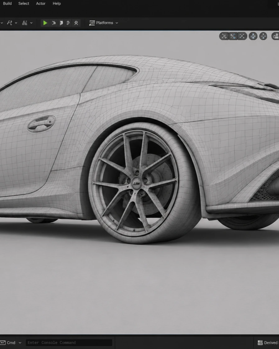
Three-dimensional wireframe development and verification of LSW forged wheels, vehicle wheel arches, and braking systems
The final effect of the gray coupe studio after completing the assembly of LSW forged wheels

Weight reduction is a choice about both material and structure.

A wheel’s weight needs to be understood in relation to its size, design and intended use. The center, spokes and rim serve different purposes; their connections and material distribution form the structure. Compare weight, load and fitment under equivalent specifications to understand the design choices more clearly.

Understand forging through structure.

We consider weight reduction in the context of the whole vehicle. Road use, performance driving and off-road travel place different priorities on a setup, while tires and brakes also affect the choice. Define the intended use first, then discuss construction and dimensions with that context in mind.

From analysis to the physical wheel.

Structural analysis helps explain stress and deformation under defined conditions. Physical tests examine a specific sample against a loading method and acceptance criteria. They offer different perspectives. Understanding a technology means looking at the problem it addresses and whether its analysis and testing apply to your chosen model and size.

We want process names to lead to a more concrete understanding: how material enters manufacturing, how structure expresses design, how dimensions relate to the vehicle and how results are documented. Explore the technical pages with these questions in mind to decide what you need to learn next.

NEXT / MANUFACTURING

How does technology enter manufacturing?

Enter smart manufacturing

NEXT / VALIDATION

How is performance verified?

View certification and testing