

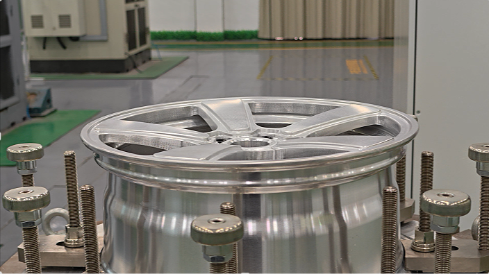
The Cornering Load Case Focuses on the Lateral Moment Path
Steering and lateral forces travel through the tyre and wheel to the mounting interface. A cornering fatigue test repeatedly applies a bending moment on a controlled rig to observe the response of the hub, bolt holes, mounting face, spokes and transition regions under cyclic load.
Fixturing and Lever-Arm Geometry Are Essential Context
Test fixturing, loading-arm geometry, target moment, speed or cycle count, fastening method and equipment calibration all affect interpretation. The report should also state the sample model, size, offset, material and manufacturing batch so that equipment capability is not misrepresented as a conclusion for the entire range.
- Relationship between the sample and final product specification
- Mounting-fastener and loading-arm setup
- Target moment, cycles and stop rules
- Applicable standard, customer specification and acceptance clause
Observe Structural Changes, Not Merely Machine Rotation
Abnormal noise, displacement, loosening or equipment stops should be recorded during testing, with interim or post-test inspections performed as required. Areas of potential interest include hub-to-spoke transitions, the vicinity of bolt holes, the mounting face and local section changes.
A Conclusion Applies Only to the Defined Sample and Method
The available media shows a cornering fatigue test rig but provides no specific moment, cycle count, sample specification or signed conclusion. This article explains the method only and does not claim that a product has passed. A formal determination requires the complete report corresponding to the target specification.
Differences in common names between bending fatigue and “rotary bending fatigue”
Bending fatigue test is also called rotational bending fatigue test in different standard systems: the wheel is fixed on the rotating spindle, and a constant bending moment is applied on its mounting surface through a loading arm to simulate the continuous lateral moment generated by the tire contact point on the wheel when the vehicle turns. The rotation process causes each point on the hub surface to bear the same stress cycle in sequence, which is a typical high-cycle fatigue loading method.
Standards such as JWL, VIA and SAE J2530 all include such tests, but the specific bending moment calculation methods, number of cycles and judgment standards are different. The test report should clearly indicate the standard version used and the corresponding sample specifications to avoid direct comparison or mixing of results from different systems.
Next Step