Request a quote
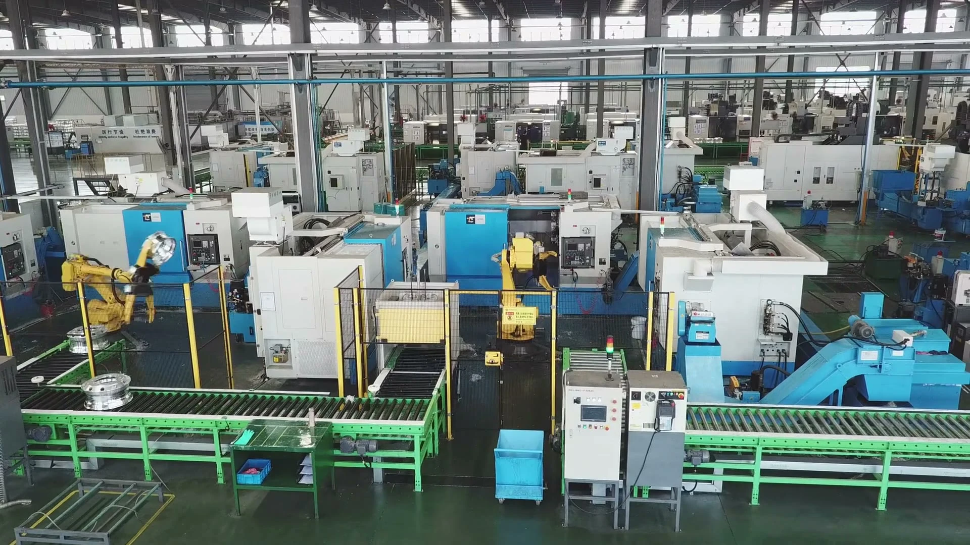
LSW manufacturing facility

LSW / MANUFACTURING

From material preparation to final inspection, explore how each stage turns a design into a physical product.

THE MANUFACTURING PROCESS

Explore each stage.
See how a wheel takes shape.

Forging, heat treatment, precision machining and finishing form a connected sequence. Follow it to understand each stage and the dimensions, appearance and quality information to review.

Explore the manufacturing process →

Core capabilities

Manufacturing stages and key checks.

Each stage receives the result of the previous one and prepares for the next. Follow material preparation, forming, heat treatment and machining to see how the design emerges. Process arrangements and inspections relate to the specific product.

A three-level forging and molding production line consisting of 6000T, 12000T and 800T forging equipment.
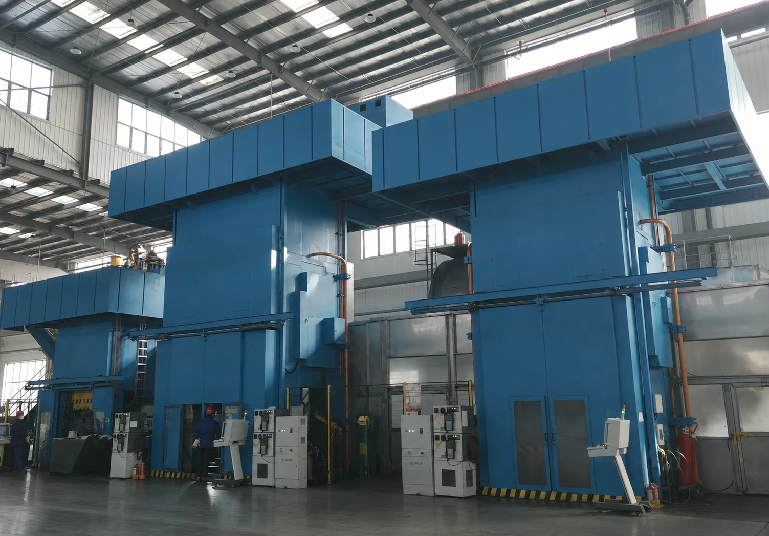
LSW wheel factory 6000T, 12000T and 800T three-stage forging and forming production lines

Three-stage forging is a sequence of operations

Available information shows a line comprising 6000T, 12000T and 800T forging presses. The important context is the role each station plays in billet preforming, main forming and subsequent sizing or process transfer—and how the workpiece remains controlled between stations. Adding the tonnage figures together does not describe product performance.

Tonnage Is Not a Quality Conclusion

Press tonnage states nominal pressure capacity. It is not the actual forming load for a particular wheel and cannot, by itself, establish strength or fatigue life. The process also depends on billet dimensions and condition, die geometry, contact conditions, temperature, the pressing sequence and equipment condition.

Progressive Forming Supports Consistent Material Distribution

Multi-stage forming can divide major geometric changes across several operations, guiding material progressively into the hub, spokes and rim while retaining suitable allowances for heat treatment and finish machining. Achievement of the intended result must be confirmed through forging dimensions, surface condition, remaining machining allowance and any required internal-quality inspection.
Learn More

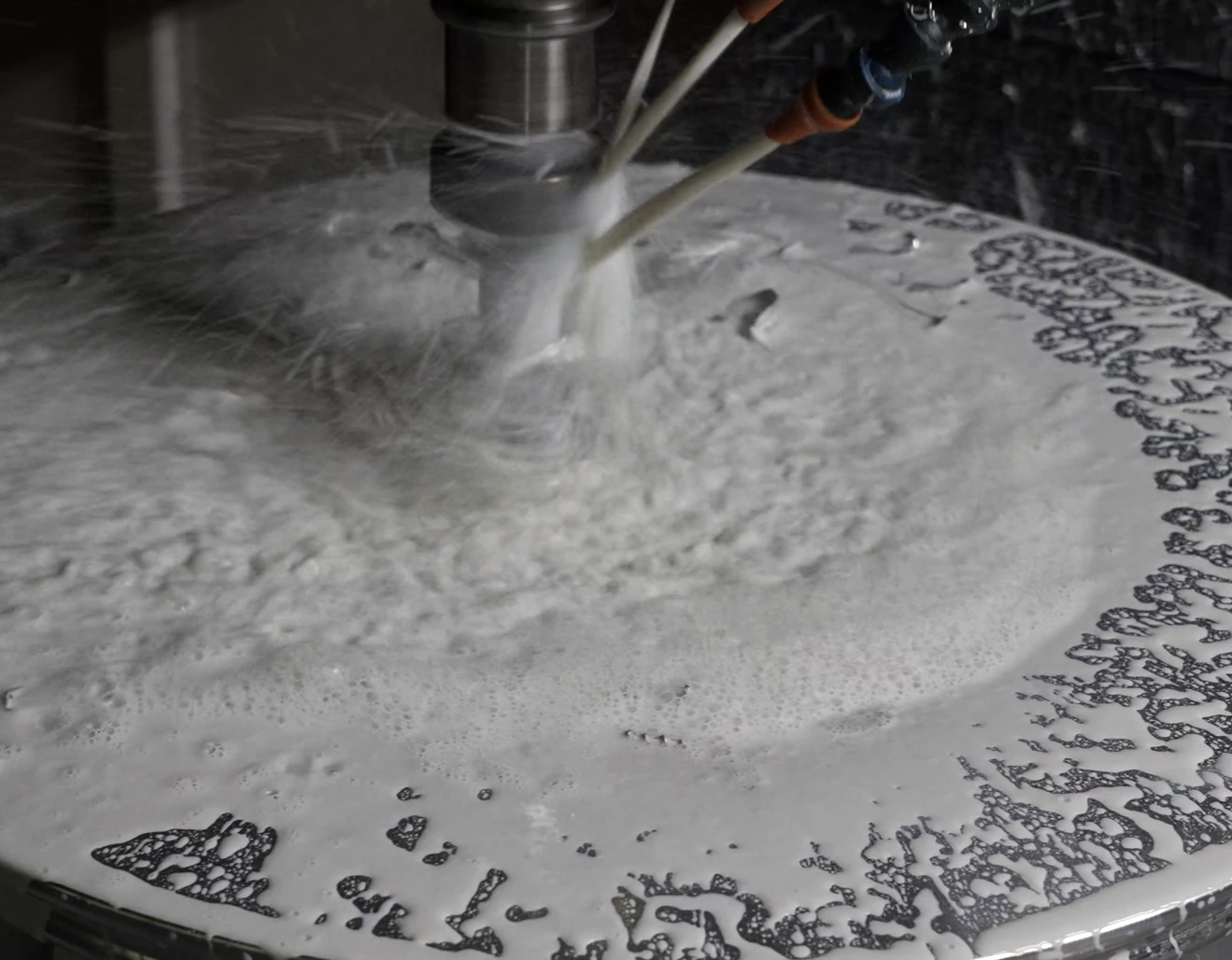
Five-axis precision machining is performed on key areas such as wheel spokes, rims, and mounting surfaces. The specific machining accuracy is subject to the official engineering drawings.

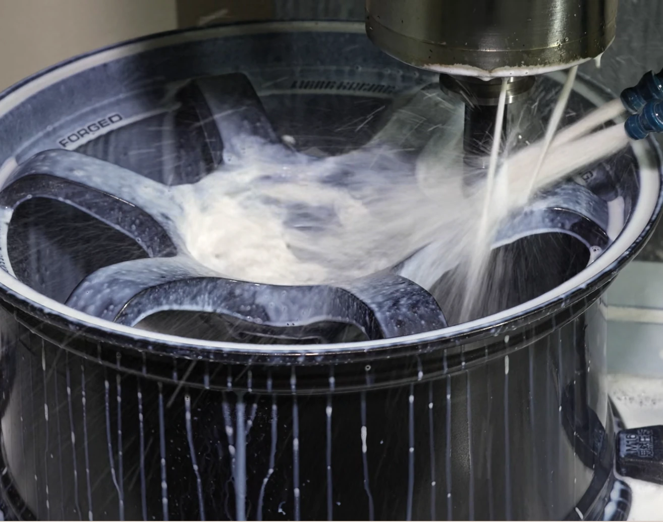
Five-axis CNC machining of an LSW forged wheel

Five axes describe machine movement

A 5-axis CNC system combines three linear axes with rotary motion to change the orientation of the workpiece or cutting tool, improving access to spoke sidewalls, windows, rear surfaces and complex transitions. It describes a machining capability; it does not automatically establish a dimension, tolerance or surface-finish result.

The Datum System Defines Geometric Relationships

Wheel machining requires consistent location and datum transfer across the mounting face, centre bore, bolt holes, rim and spokes. If the fixturing method cannot reproduce those datums consistently, the same programmed tool path can still produce positional or geometric variation.

Program, Tooling and Measurement Form a Closed Loop

The CNC program defines the path, tool condition affects the actual cut, and measurement results determine whether compensation or a process stop is required. Different regions may use different roughing, semi-finishing and finishing strategies. Tolerances, surface roughness and inspection frequency must follow the product drawing and quality plan.

Learn More

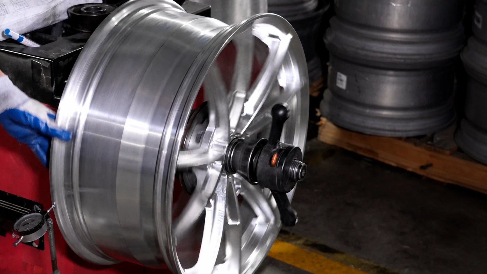
Specialist equipment measures radial and lateral runout to check rim geometry during rotation. Acceptance criteria follow the formal engineering drawing.

Dial indicator measuring rim runout on an LSW forged wheel

Runout and imbalance are different issues

Radial runout describes the deviation of the rim circumference relative to the rotation axis, and end face runout describes the flatness deviation of the rim side relative to the rotation axis; both reflect the geometric accuracy of the wheel itself, which is usually measured during the production process through special testing equipment combined with a dial indicator or laser probe. Dynamic balancing describes whether the mass distribution of the wheel (usually together with the tire) is uniform relative to the axis of rotation. Even if the runout of a wheel is completely within the tolerance range, if the mass distribution is uneven, dynamic balance correction is still required through counterweights.

Why both affect the steering experience

Excessive radial or end face runout will cause periodic height or angle changes in the tire contact point in each revolution. Even if the dynamic balance is good, the driver may still feel periodic vibrations in the steering wheel or body, and this vibration usually cannot be eliminated by adding or removing counterweights. The cause needs to be found from the geometric accuracy of the wheel or the tire itself. Imbalance is more manifested as steering wheel or seat vibration that increases as the vehicle speed increases, which is a typical symptom that dynamic balance correction should solve.

Key points for dynamic balance correction during installation

After the wheel and tire are assembled, it usually needs to be tested on a dynamic balancing machine, and weights should be pasted or installed on the inner and outer sides of the rim according to the displayed imbalance amount and angle. Before testing, it should be confirmed that the wheel has been correctly positioned on the spindle of the dynamic balancing machine to avoid additional measurement deviations due to positioning errors; the positioning methods and weighting schemes of different dynamic balancing equipment may be different, and the specific operations should follow the standard procedures of the equipment manufacturer and store.

Learn More

The hub number is associated with material batches, production processes and inspection records. The specific traceability scope is subject to the actual system of the enterprise.

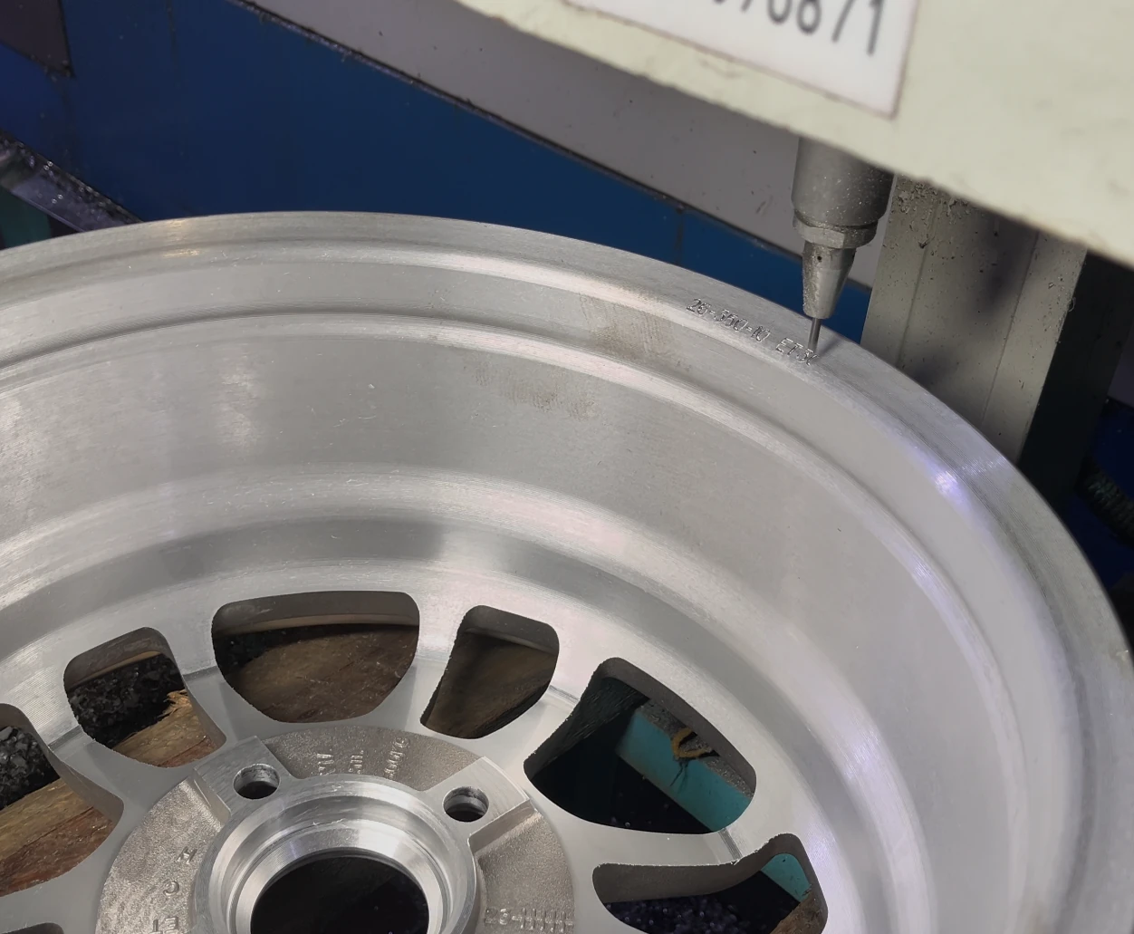
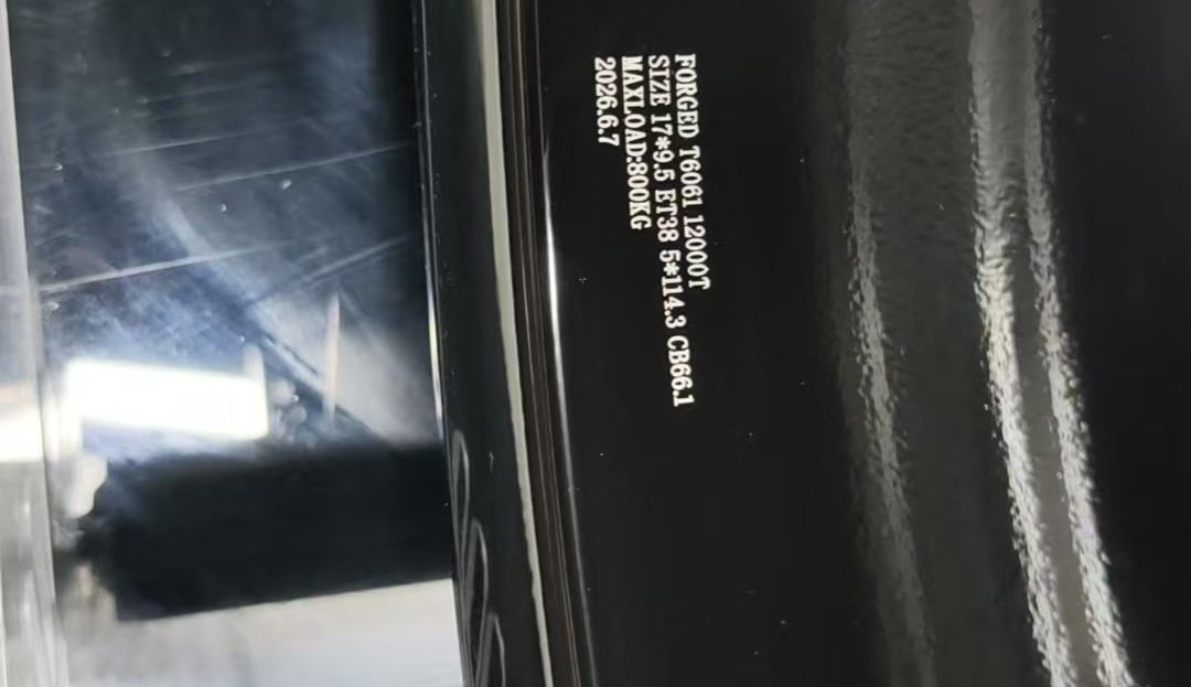
During the production process of LSW forged wheels, the batch number and traceability mark are engraved on the inside of the rim.

Separate Test Capability from Certification Conclusions

The presence of a particular test system at a factory does not mean that every product specification holds the corresponding certification. Test methods, conditions, sample specifications and documented conclusions should be stated separately, so that brand-level claims never replace product-specific evidence.

What a Verifiable Document Must Establish

A material report should link the grade to its batch. A test report should identify the sample, method, conditions, date and conclusion. A management-system or product certificate should state its number, issuer, covered entity, scope and current validity. An icon without a stated scope does not establish whether a specific specification is covered.

Understanding manufacturing information for your specification

Press capacity, machining tolerances, inspection details and traceability information should be read alongside the relevant equipment records, product drawings and quality documents. To ask about a particular model or order, share the model, dimensions and intended use so the relevant information and its scope can be confirmed.

Learn More

Manufacturing Chapters

Manufacturing Process File

Select a stage to explore its purpose, process and key checks.

Process screen / 01
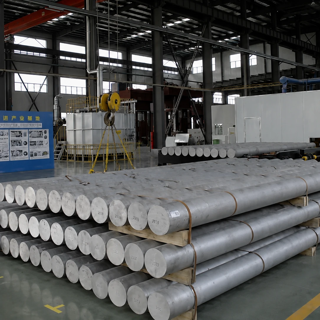
6061-T6 aluminum alloy round bar raw materials neatly stacked in the LSW forged wheel factory
Incoming 6061-T6 Aluminium Alloy

Current Operation / 01

Incoming Material

After the raw materials enter the factory, the grade, batch, size and appearance are inspected, and the material batch association is retained.

Each stage receives the result of the previous one and prepares for the next. Follow material preparation, forming, heat treatment and machining to see how the design emerges. Process arrangements and inspections relate to the specific product.

Documentation Status
Material and Batch Information
Quality Gates
Composition, size and appearance inspection
Traceability
Material batch association

Validation Centre

Made.
Then verified.

Reserve images and reporting locations for road load, impact, size and environmental verification, and formal conclusions are released according to specific specification documents.

View data and verify boundaries

Hub radial fatigue durability test

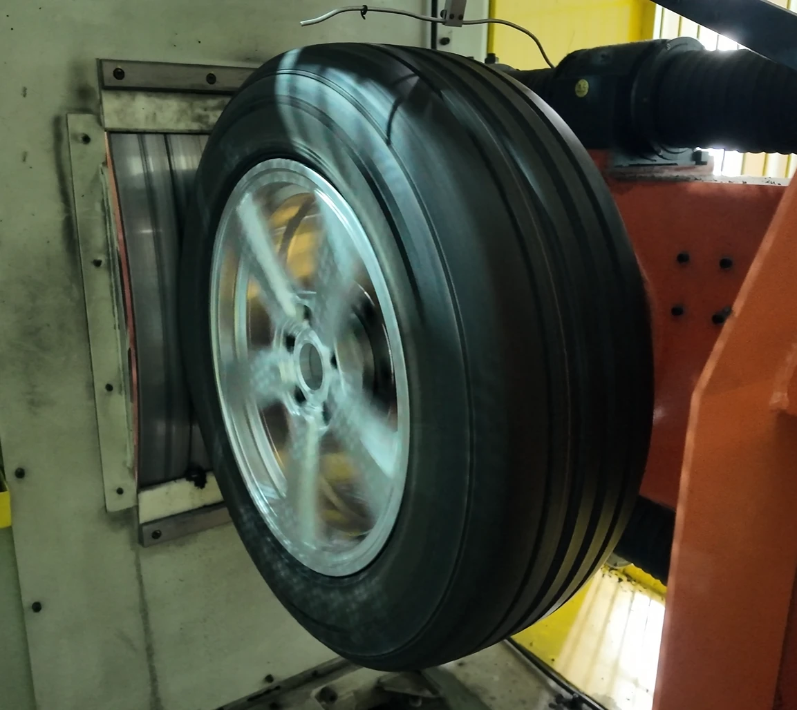
LSW forged wheel radial fatigue testing machine is undergoing tire load endurance testing

The Test Simulates Sustained Radial Rolling Action

A radial fatigue test typically places a tyre-and-wheel assembly on test equipment, applies load and rolls it continuously so the rim and spokes repeatedly experience radial loading representative of straight-line driving. It evaluates durability under cyclic action; it does not reproduce every load condition encountered on the road.

Input Conditions Determine Whether the Result Can Be Interpreted

The report should identify the sample and specification, tyre and inflation conditions, mounting method, load setting, cycle requirement, stop conditions and applicable standard or customer specification. Without that context, footage of the equipment running cannot establish a result, and the conclusion for one sample cannot be extended to the full product range.

Process Monitoring and Post-Test Inspection Are Equally Important

Equipment and sample condition should be monitored as specified throughout the test, with anomalies, stops and adjustments recorded. After the required procedure, the rim, spokes and mounting area must be inspected for cracks or abnormal deformation as the method requires, with images and records linked to the sample.

Learn More
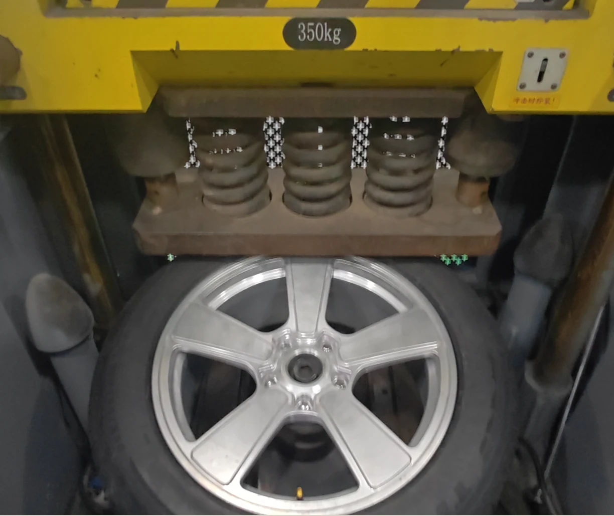
LSW forged wheel impact testing machine is performing impact testing on aluminum alloy wheels with tires

Impact Testing Examines a Short-Duration High Load

Unlike the sustained cycles of a fatigue test, an impact test uses defined conditions such as mass and drop height to create a transient event and observe the structural response of a tyre-and-wheel assembly in a specified setup. The 13° angle is one geometric condition used in common test arrangements and cannot be interpreted apart from the complete method.

Impact Energy Comes from a Controlled Set of Inputs

Before testing, the sample, tyre, inflation pressure, mounting orientation, impact location, impactor condition and method requirements must be confirmed. Drop mass, drop height and any other energy settings must come from the applicable standard, specification or customer requirement. This site has not received those figures and makes no assumptions about them.

Post-Test Inspection Determines How a Conclusion Is Reached

After impact, the applicable method should be followed to inspect tyre retention and any visible damage, cracking, separation or abnormal deformation of the rim and spokes, with findings recorded against the method’s definitions. Photographs can support traceability but do not replace the prescribed acceptance procedure.

Learn More
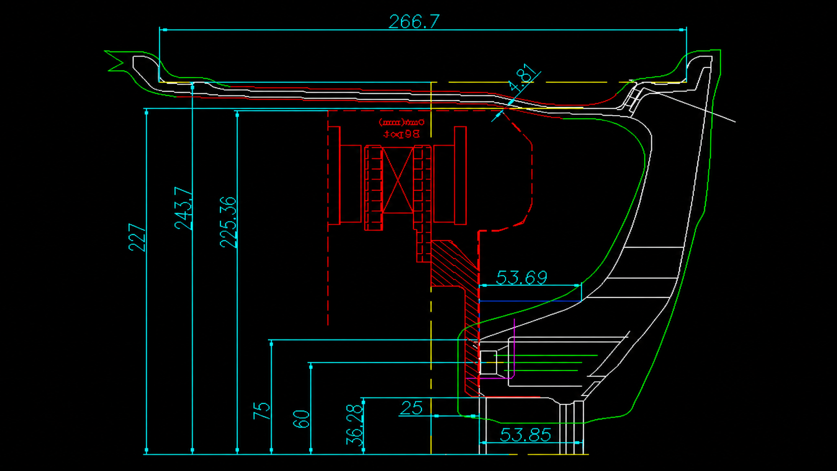
LSW forged wheel engineering cross-section and key dimensions

Runout and imbalance are different issues

Radial runout describes the deviation of the rim circumference relative to the rotation axis, and end face runout describes the flatness deviation of the rim side relative to the rotation axis; both reflect the geometric accuracy of the wheel itself, which is usually measured during the production process through special testing equipment combined with a dial indicator or laser probe. Dynamic balancing describes whether the mass distribution of the wheel (usually together with the tire) is uniform relative to the axis of rotation. Even if the runout of a wheel is completely within the tolerance range, if the mass distribution is uneven, dynamic balance correction is still required through counterweights.

Why both affect the steering experience

Excessive radial or end face runout will cause periodic height or angle changes in the tire contact point in each revolution. Even if the dynamic balance is good, the driver may still feel periodic vibrations in the steering wheel or body, and this vibration usually cannot be eliminated by adding or removing counterweights. The cause needs to be found from the geometric accuracy of the wheel or the tire itself. Imbalance is more manifested as steering wheel or seat vibration that increases as the vehicle speed increases, which is a typical symptom that dynamic balance correction should solve.

Key points for dynamic balance correction during installation

After the wheel and tire are assembled, it usually needs to be tested on a dynamic balancing machine, and weights should be pasted or installed on the inner and outer sides of the rim according to the displayed imbalance amount and angle. Before testing, it should be confirmed that the wheel has been correctly positioned on the spindle of the dynamic balancing machine to avoid additional measurement deviations due to positioning errors; the positioning methods and weighting schemes of different dynamic balancing equipment may be different, and the specific operations should follow the standard procedures of the equipment manufacturer and store.

Learn More
LSW black forged wheels with laser-engraved specifications, load and production traceability information on the inside

Separate Test Capability from Certification Conclusions

The presence of a particular test system at a factory does not mean that every product specification holds the corresponding certification. Test methods, conditions, sample specifications and documented conclusions should be stated separately, so that brand-level claims never replace product-specific evidence.

What a Verifiable Document Must Establish

A material report should link the grade to its batch. A test report should identify the sample, method, conditions, date and conclusion. A management-system or product certificate should state its number, issuer, covered entity, scope and current validity. An icon without a stated scope does not establish whether a specific specification is covered.

Understanding manufacturing information for your specification

Press capacity, machining tolerances, inspection details and traceability information should be read alongside the relevant equipment records, product drawings and quality documents. To ask about a particular model or order, share the model, dimensions and intended use so the relevant information and its scope can be confirmed.

Learn More

From dimensions on a drawing to a finished product.

Manufacturing connects design with a physical product. Material preparation, forging, heat treatment and precision machining each have a role, and the condition left by one stage affects later work and inspection. To understand manufacturing capability, start with the full sequence, then look at key dimensions, surface quality and inspection methods.

Manufacturing detail shapes the finished wheel.

We value coordination between the spoke profile and the mounting areas. The face expresses the design, while mounting surfaces, holes and rim dimensions are central to configuration checks. Connecting visible details with dimensional requirements reveals how a wheel moves from a visual concept toward practical use.

Make every check specific.

Appearance, dimensions and rotational behavior offer different views of a finished wheel. Surface inspection considers color, texture and visible detail; dimensional inspection follows engineering requirements; runout and balance checks each use their own methods. Together they support quality discussions, with results that an equipment photograph alone cannot establish.

For custom or batch enquiries, discuss the vehicle, size combinations, finish and required documentation alongside design and quantity. Setting these out at the start keeps the conversation centered on one brief and helps identify the checks needed at sample, production and delivery stages.

VISIT / PARTNERSHIP / ENGINEERING

Want to know more
LSW manufacturing system?

Contact the manufacturing team