

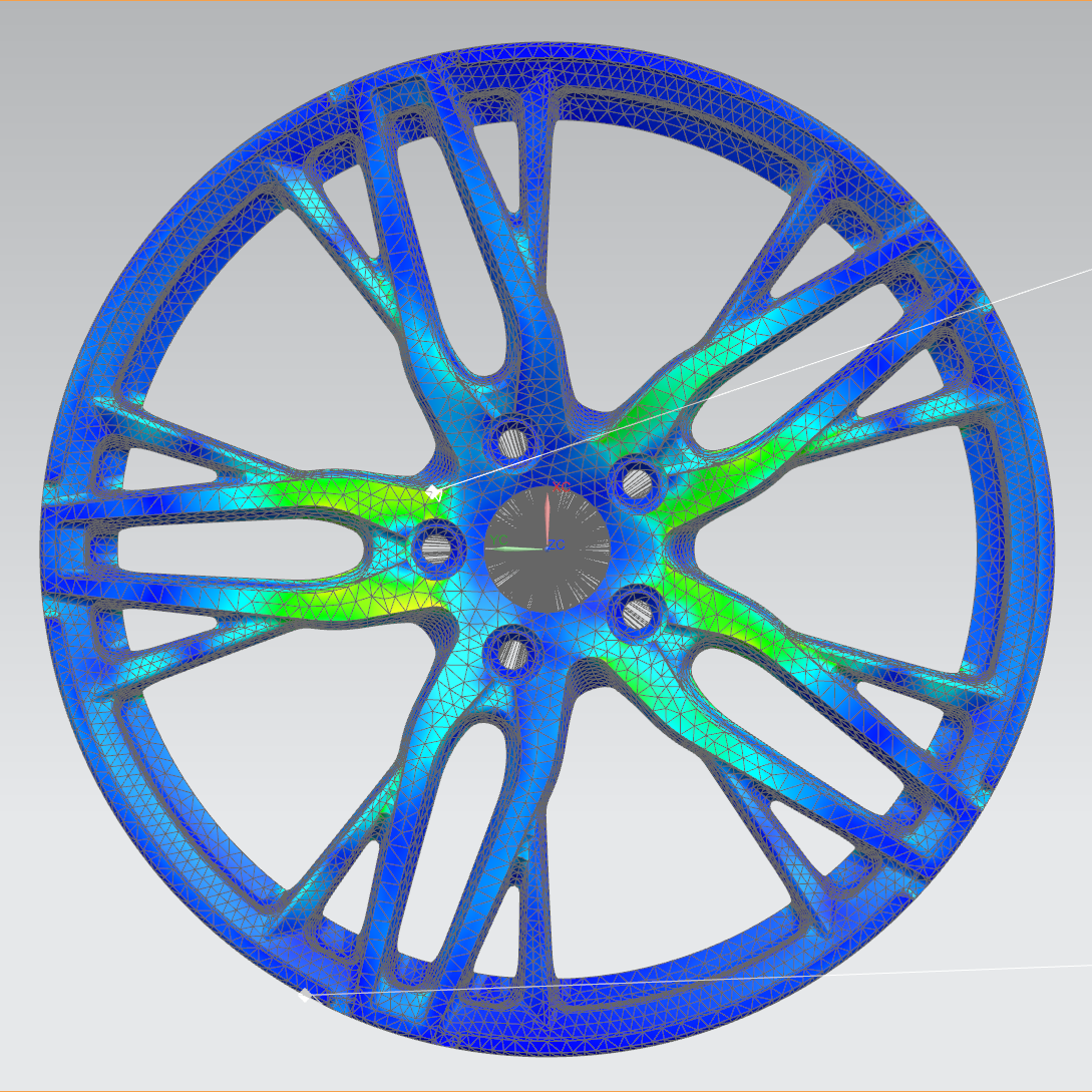
Analysis Begins with Boundary Conditions
A finite-element model must define material properties, interfaces, constraint locations and the way loads are applied. Radial, cornering and impact load cases are different; calculation results are meaningful for engineering purposes only when the boundary conditions correspond to the intended load case.
First, Understand How Loads Travel
The analysis is not limited to finding a single maximum value. It also examines how loads travel from the mounting face through the hub and spokes to the rim, and whether changes in local stiffness create unnecessary stress concentrations. Mesh quality, contact definitions and geometric simplifications also affect the result.
- Constraint relationship between wheel center and mounting surface
- Stress and displacement trends in spoke transition zone
- Local response of rim area
- Relative changes between different structural versions
Give Each Iteration a Clear Purpose
The engineering team can revise spoke sections, fillets, thickness transitions and back-milled areas, then compare the designs under the same load conditions. Weight reduction requires a clear understanding of load paths and compliance with structural requirements; colour plots alone are not a basis for removing material.
Simulation Does Not Replace Physical Testing
Finite-element analysis helps screen design directions and reduce unproductive iterations. The final product still requires dimensional inspection, material and process verification, and the relevant physical validation for its specific specification. Contour plots shown on this site illustrate the analysis method and do not constitute a test result for any product specification.
Common analysis output and relative comparison methods
Finite element analysis usually outputs relative indicators such as stress distribution (such as equivalent stress), displacement and safety factor, which are used to compare the performance of different structural solutions under the same working conditions, rather than directly outputting the fatigue life or final qualification conclusion of the wheel. The engineering team generally uses the baseline plan as a reference to observe whether the stress concentration area is improved and whether the displacement converges within an acceptable range after structural adjustment.
Methods such as topology optimization and morphology optimization can assist in identifying areas where materials may be redundant under given load and constraint conditions, and provide a directional reference for back milling weight reduction, but the final section, fillet and thickness still need to be determined in combination with the manufacturing process, mold capabilities and physical verification.
Next Step